Showing posts with label Arduino. Show all posts

Friday, December 27, 2013

STIGA table hockey custom scoreboard

Hi there ! First of all merry Christmas and happy new year. I am sorry that I wasn’t active for a long time, but things have changed lately. I had to overcome some things, I can’t tell you whether I’ll continue with this blog, but for right now I want to.


So, few weeks back my brother had called me, and he said that he would like to restore an old STIGA table hockey, that we used to play with, when we were younger. I thought it was a great idea, so he wanted me to create a scoreboard, since game itself had only mechanical one that was not very appealing. They also came up with new goals and nets for them and we’ve ordered original NHL teams. So when designing I went for the easier option, so I have found these I2C display modules, because multiplexing eight 7-segment displays with single atmega328 would be suicide. They came right before Christmas, and I brought home with me few tools to put it all together. It wasn’t as easy as though at the beginning since library provided by the seller wasn’t directly for the version of the displays we’ve ordered. That’s the reason why it took me some time to figure it all out. After that it was pretty straight forward. You can see the working scoreboard in the video, also Brandon Dubinsky scoring brilliant goal !


Sunday, March 31, 2013

Portable Power Supply


Hi ! First of all happy Easter to everyone. If you haven’t seen it yet, go watch my reel, I hope you’ll like it.


Currently I’m working on a project that uses Raspberry Pi, but it requires Pi to be portable. This raises a question of power supply. Of course, I could just use 4 AA batteries or something temporary, but idea of portable power supply has been in my mind for some time. Once again I decided to use Nokia LiPo batteries, since they are great, and I have a lot of them. I used 3 x 1500 mAh ones so it gives me about 4.5 Ah to work with, which is not bad at all. At ebay I found these 3.7V to 5V booster converters, they’re great so I’ve already bought two of them. There was some problem with grounding, because circuit wasn’t working after resetting, so I had to connect battery and output ground with schottky diode, which solved the problem. I decided to put it all in an altoids tin. I still have lot of them from the times when I was building portable circuits. I have to say this thing is a beast, it has no problems with powering things like Arduino, Raspberry Pi or even charging my phone. Only problem is that circuit doesn’t have control of how much is being drawn from batteries, so when I’m charging my phone, circuit is giving out something like 1 ampere, and it gets really hot immediately. But that doesn’t matter since I will only be using it on my bench. Having handy 5V supply available every time is great.


Saturday, February 9, 2013

Observer Reboot [2.0]


Hi ! First of all I want to apologize for not being active for quiet some time. I was working on something big, but it was going slow so I had to make a break and I decided to reboot the observer !


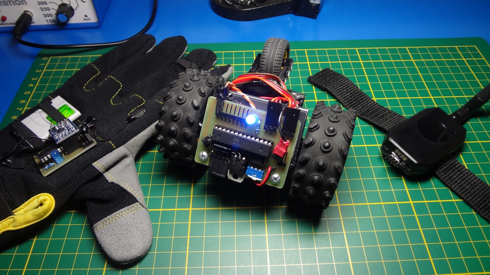
Year ago I lost all of my data including code that was on observer, since that I'm storing all of my data on cloud, and a usb drive aswell. So when I was wondering what could I do with xbee modules, I thought that I could finally write some new code for observer, but at the same time I wanted to make some improvements. So I decided to use control glove, which has a lot of potential, even more now since I've added bend sensor to the index finger. So I've built small bracelet that has xbee inside and antenna. I etched new board for observer, which used a transistor to control whether servos are on or not, but that wasn't working quiet well because transistor wasn't able to provide enough current and to switch servos fast enough and it caused servos to jitter. Reason was that control glove sends data every 50 ms and observer refreshes itself every 45ms in order to make turning and speed control smooth enough. I am also using two power supplies now, because I like to separate logics from servos. It was quiet hard to synchronize data sending/receiving, and as you can see in the video it's far from being perfect.


This is the first time I've decided to make a proper narrated video, so please let me know what you think of it, because if it's bad I will return to the old way of doing short videos with music in background. So if you liked it please like it or let me now in the comments. As for my future plans, I'll get back to that big secret project and I hope, it won't take me lot of time to finish it.

Friday, September 28, 2012

Bracerbot Beta UI

Hi there ! I'm back with another update. 


This time I finally focused on sending data from bracerbot to PC via Bluetooth. At the same time I've written small application in Processing that acquires the data and displays them on the screen using controlP5 library, which is great. This application also allow you to control robot. So in next week or so I will finally program gait and make this application look kinda better. Also notice that light sensor is showing 1023 because its not yet soldered to the board.

Tuesday, September 18, 2012

Bracerbot Beta [update]

Hi ! First of all I want to thank all of you for 15,000 views ! and I just want to show this quick update.

Finally he's walking ! Still need to work on it though. I've also spay-painted legs to black I think it looks much better. I'm still wondering whether I should keep is as it is or create some case for batteries from acrylic. Well gait is currently priority, but I also want to start with data acquisition. Then I want to make Processing app with full movement control and then perhaps I will try to make Android app in eclipse. 

Sunday, September 2, 2012

Bracerbot Beta

Hi there ! I am so sorry that it took me so long, but finally Bracerbot is here, Even though it's still in beta mode.


It all began early in July when I was thinking about what should I build next. I was positive that I wanted a quadruped, but there's lot of them, so I wanted mine to be somehow special. Since Iron Man is my favorite hero I always dreamed of building something that I could actually wear. Well what could I wear was question then. I ended up choosing bracelet (sort of). After that I've ordered some servos from ebay and started to draw some ideas in sketchup. It took me a week to make a final design. Then I started to put it all together. It uses 2xNokia batteries (I love those !) for board, bluetooth and sensors and 4x1.5V AAA batteries for servos (one battery in one leg, seemed like a good idea before I had to make wiring). You can see process of transformation in video. Currently I'm programming walking and I think it'll take me some time. I'm also thinking of using some sort of thin plastic as a mask, because as you can see it doesn't look very nice. To be honest I like the idea, but overall I think I failed because robot is too heavy as a bracelet (around 300 grams) and it doesn't look very nice as-well. So there will be some updates as I proceed with programming and Raspberry Pi still haven't arrived yet so I'm waiting.


Tuesday, July 10, 2012

Voice Controlled Light

Hi there ! First of all Happy Nikola Tesla Day ! And secondly I would like to apologize for not being active for some time.


But since summer is here I will hopefully have more time to work on my projects. Today I want to show you sort of an Intro. Finally I had some extra money so I've bought some relays. For quiet some time I have this idea in my mind. It's an idea to change my room in one big ecosystem, that would preferably be controlled by voice via PC or Android phone. Yes once again this idea comes from Ironman. So I've build simple setup in a box and connected arduino with a Bluetooth module to it and wrote some simple code to look for word “light”. You can see the result in a video. Google voice recognition seems to work pretty fast, but you need to have internet connection in order to use it. That's the reason why I want whole system to be controlled from my desktop. So I need to find right voice recognition software and install a microphone somewhere.

Tuesday, June 12, 2012

Control Glove as Game Controller


Hi there. Sorry for bit of a delay, but I'm unable to buy new Bluetooth module for dummy and there are few other problems with it. So sadly, I am forced to postpone this project for some time.


But don't worry I'm still working on Control Glove, because I feel that it has some potential. Since I have nothing to control in real world, I've been thinking what different can I control. When I lack creativity (most of the time), I'm playing some classic PC games from my childhood. I've been playing Re-Volt once again and it suddenly hit me, I can create sort of a game controller. Well that's easy to say, but harder to do. For some time I was totally lost. But then I found out that I can trick it. It basically works the way that Control Glove sends data from accelerometer to PC via Bluetooth. That data goes to a Application written in Processing. Processing is great, because you can export application directly for Windows/MAC/Linux. I have used a little trick, when you turn you hand to the left, processing will send (VK_left) via java Robot when you turn hand to the right Robot will send (VK_right). I found this to be the easiest method. Of course is not the best solution. Right now I'm planning to add few buttons to the glove to make proper controller out of it.


Wednesday, May 16, 2012

Control Glove


Hi there. First of all I would like to thank all viewers because recently I hit 40.000 views on videos on my youtube channel and also 10.000 views on this blog. So few weeks ago I showed you beta of dummy, well I haven't been working on it so much since, I just made a PCB, but I've been working on this glove.


You might ask why glove ? Well because I always wanted to make one and I couldn't think of a better way of how to control Dummy. Even this glove is still in sort of beta state. It uses Atmega8 with the bootloader that has BOD (Brown-out detection) level set to 2.7V so this board can easily operate at 3.3 volts. I chose this option because of the fact that I wanted to implement battery to glove and that meant, that battery has to be small and light. I chose a battery BL-5B from an old Nokia. If you have one of these phones just laying around use that batteries, they have lot of power and 3.7 volts is all that you need. Board also have headers for FTDI or Bluetooth module, which operates at 3.3volts. Accelerometer that is for now the only sensor on this glove, operates also at 3.3volts which gave me the opportunity to use that Nokia battery and 3.3v regulator. Remember that when you are using different than 5V power source you have to put power on AREF pin and in the setup of the code declare that you are using EXTERNAL analog reference. In the future I would like to add few more sensors (probably flex). So I hope you like it and once again thanks for your support.


Sunday, April 22, 2012

Dummy Pre-Alpha


Few weeks ago I started working on a robotic hand, it's still in pre-alpha phase, because of the claws that are not yet operational, but I wanted to show you my progress.


Well, you may wonder why to call it Dummy ? Its name comes from the Iron Man movie, where Tony Stark has a robotic helper but it's not working well so it completely fits to my arm. I'm still working on a way how to send data from controller (which I would like to implement to a glove) to hand itself. I wrote some code for sending data in a packet form, because I would like to make the whole arm wireless. Problem is that I have to send positions of all 4 servos (now it sends just position for two of them). This project is definitely more complex than I've expected, so it's going to take me more time to finish it, and that's the reason why there will be more smaller updates.


Monday, February 27, 2012

Observer 1.4 [update]

Hi there. I am presenting you version 1.4. 


The mayor change is that I’ve added third wheel to the back. I’m still experimenting with that but as you can see in the video observer can now drive over various obstacles without any problems. Also I moved Bluetooth module under the PCB to use the space that was there. Right now I’m drawing new PCB for observer, so that means next update will be version 2.0. I don’t want to spoil it, so I just say there’s going to be multiple sensors and when all will work out well I believe that version 2.0 will be awesome.


Sunday, February 12, 2012

Observer 1.3 [update]

Bluetooth module has arrived, so I want to show you pics of another update. 


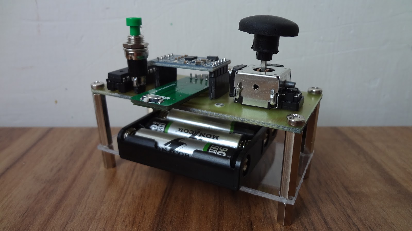
Reason that version 1.2 is missing is that this version (controller) was build on breadboard. At first I thought that I would put controller in some case, but then I decided to leave it like this. So what’s new? I’ve added analog stick that I’ve desoldered from old gamepad. But there’s still option to control robot via accelerometer. For that purpose I’ve used pushbutton that is part of analog stick. There’s still one breaked-out analog pin on Observer waiting for some sensor. I’ve been trying to add there LM335, but I’m dealing with analog reference issue. I found out that AAA batteries aren’t very good for such robot and that having separate power sources for servos and for microprocessor would be much better.


Sunday, January 29, 2012

Observer 1.1 [update]

It took me more time then I've expected, but here's and update.


I have used second Arduino (Duemilanove) as an controller. For now robot is being controlled via laptop, but I have already ordered second bluetooth module for standalone controller. I thought adding LED's as front lights would be cool also.

Sunday, December 11, 2011

Observer Alpha

So I was finally able to build my first driving robot.  


It's still an Alpha version so it has no special functions but in future I would like add more sensors and maybe even a digital camera that will record what's going on around. Since this is just first release I won't put here any code or tutorial but I will be updating this post. 

Monday, November 21, 2011

Servo etcher

Since I like to fabricate my own PCB’s, it’s obvious that I etch a lot. For that purpose I’m using old CD container.


Thing that I hate is that the whole process is slow and ineffective. Thus I’ve decided to use one of the servo’s that was lying around. I’ve hot glued servo to the plastic cover of CD container. All I needed then was to program an Arduino, so it could change speed of servo with a values that comes of a potentiomer.
(Code I'm using is "Knob" from Arduino IDE Servo library) 


Sunday, October 30, 2011

Evil Pumpkin

I'm from Europe and we’re not celebrating Halloween, but I always wanted to carve a pumpkin.

So I’ve bought one and I carved it. At first I thought that a simple candle inside would be enough, but then I decided to go with arduino, LED, speaker and distance sensor. I’ve used my Nano, and for sensor I used my IR sensor. Here’s the video and code.


code:
int IRSense = A0;
int IRTrans = 2;
int Flick = 10;
int valueAmbient = 0;

void setup() {
 pinMode(IRSense, INPUT);
 pinMode(IRTrans, OUTPUT);
 digitalWrite(IRTrans,LOW);
}

void ambient()
{
 digitalWrite(IRTrans,HIGH);
 delay(20); 
 valueAmbient = analogRead(IRSense);
 delay(20);
}

void loop() 
{
 ambient();
 digitalWrite(IRTrans,LOW);
 delay(20);
 int value = analogRead(IRSense);
 int value2 = round(value - valueAmbient);
 int dist = (((value2+15.0)/(value2*(value2+100.0)))*2000.0);
 if(dist<20) 
  {
   analogWrite(Flick,random(0,256));
   tone(8, 38);
  }
 else
  {
   analogWrite(Flick,0);
   noTone(8);
  } 

Sunday, October 16, 2011

Arduino wireless sketch uploading via Bluetooth

Few months ago I’ve showed you my Bluetooth Xbee module. Back then I was able to send some commands through it to Arduino. But I wasn’t able to upload code wirelessly. 


I’ve been trying to solve this problem and I was successful. I found out that the issue is resetting the board. Since with this setup I’m not using USB connection I can’t use DTR pin on FTDI chip. So the trick to hold a reset button press upload and when information about size pops up just wait second or two and release the reset button. Right now I’m working on some sort of method (software or hardware) to make it automatic. I also found out that the baud rate of Bluetooth module and com port on your PC must be same as the uploading speed of the board you are using. For instance I’ve been using Arduino Duemilanove for this demonstration. Its upload speed is 57600. So I had to change baud rates of Bluetooth module and com port to 57600 as well. If you’re using laptop with a Bluetooth or pc with some USB Bluetooth module you need to buy only one module for your Arduino. You don’t even need to buy Xbee shield, because this particular one works if you connect just TX,RX,3v3 and GND pins. I was trying to use it with standalone Atmega8 but for some reason it didn’t worked so I’m also working on that. If you’re trying to achieve same thing and you’re having some issues with setup or whatever just contact me. And don’t forget to watch the video.

Thursday, September 29, 2011

LM335 + Arduino temperature sensor

Few weeks ago I’ve bought a LCD 16x2 display. I wanted to create a room temperature sensor. 


I’ve been using pocket arduino and there’s been some issues with resetting. I had to burn bootloader once again, so it took me longer to make this post. Also I’ve picked LM35 for this project (cool but expensive), but I’ve burned it. So I was forced to go with LM335 (not that cool but cheap). You can download code and watch video below. 

Code : 

#include <LiquidCrystal.h>
float raw;
float temperature;
LiquidCrystal lcd(3, 4, 5, 6, 7, 8);
byte degree[8] = 
{
B01100,
B10010,
B10010,
B01100,
B00000,
B00000,
B00000,
B00000
};

void setup()
{
  lcd.begin(16, 2);
  lcd.print("Temperature :");
  lcd.createChar(0, degree); 
  lcd.setCursor(7,1);
  lcd.write(0);
  lcd.setCursor(8,1);
  lcd.print("C"); 
}

void loop()
{
 raw = analogRead(0);
 temperature = ((raw*480.0/1024.0)-273); 
 lcd.setCursor(1,1);
 lcd.print(temperature);
 delay(500);
}


Sunday, September 18, 2011

Sound/noise sensor for Arduino

For quite some time I’ve been looking for some sort of sound or noise sensor. I had some electrolytic microphones lying around, so the only problem was amplifier. 


Well you can choose either some IC or some simple transistor ones. At first I’ve tried LM386, but I found out that it’s not very good. The reason is that this IC is not meant to be used as a pre-amp. I’ve decided to use this single transistor setup with 2N3904. I’ve also bought big white board and drawn the circuit. It’s really cheap sound/noise detecting sensor and it work’s good.

Arduino code :

void setup()
{
 Serial.begin(9600); 
}

void loop()
{
 int minimum = 1024;
 int maximum = 0;
 for(int i=0;i<1000;i++)
 {
  int value = analogRead(A0); 
  minimum = min(minimum, value);
  maximum = max(maximum, value);
 }
 Serial.print("noise=");
 Serial.print(maximum-minimum);
 Serial.println(); 
}


Saturday, September 10, 2011

Pocket Arduino

Well, I have to admit that I’m little bit obsessed with Arduino clones. I always wanted to create my own pocket portable Arduino. 


I thought that Altiods tin would be perfect housing for such a project. I also had one ATmega328 laying around. There were few abilities I wanted my pocket Arduino to have. Since I wanted my Arduino to be pocket or let say portable there should be some sort of power source inside. I quickly chose 9V battery for that purpose, because arduino itself doesn’t have that big power consumption and there are still pins that I can use for other voltage input. Then I needed somehow to upload code to Arduino, so I needed some way to communicate between Arduino and PC. I chose one of that small USB to TTL converters. Keeping in mind that this Arduino has to be portable I’ve desoldered female USB type D connector that was there and replaced it with male USB connector. With this option I don’t need any USB cable, (maybe USB extender if you don’t have laptop) I can just plug the whole Altoids tin inside my PC. Another thing I wanted was small breadboard, because that’s the thing that makes Arduino portable. There were more things I wanted to have there, but even with these, it was really hard to close the tin after I've placed everything inside. But after all I’m really satisfied with the success. Arduino is fully operational, portable and still looks like mints case.